
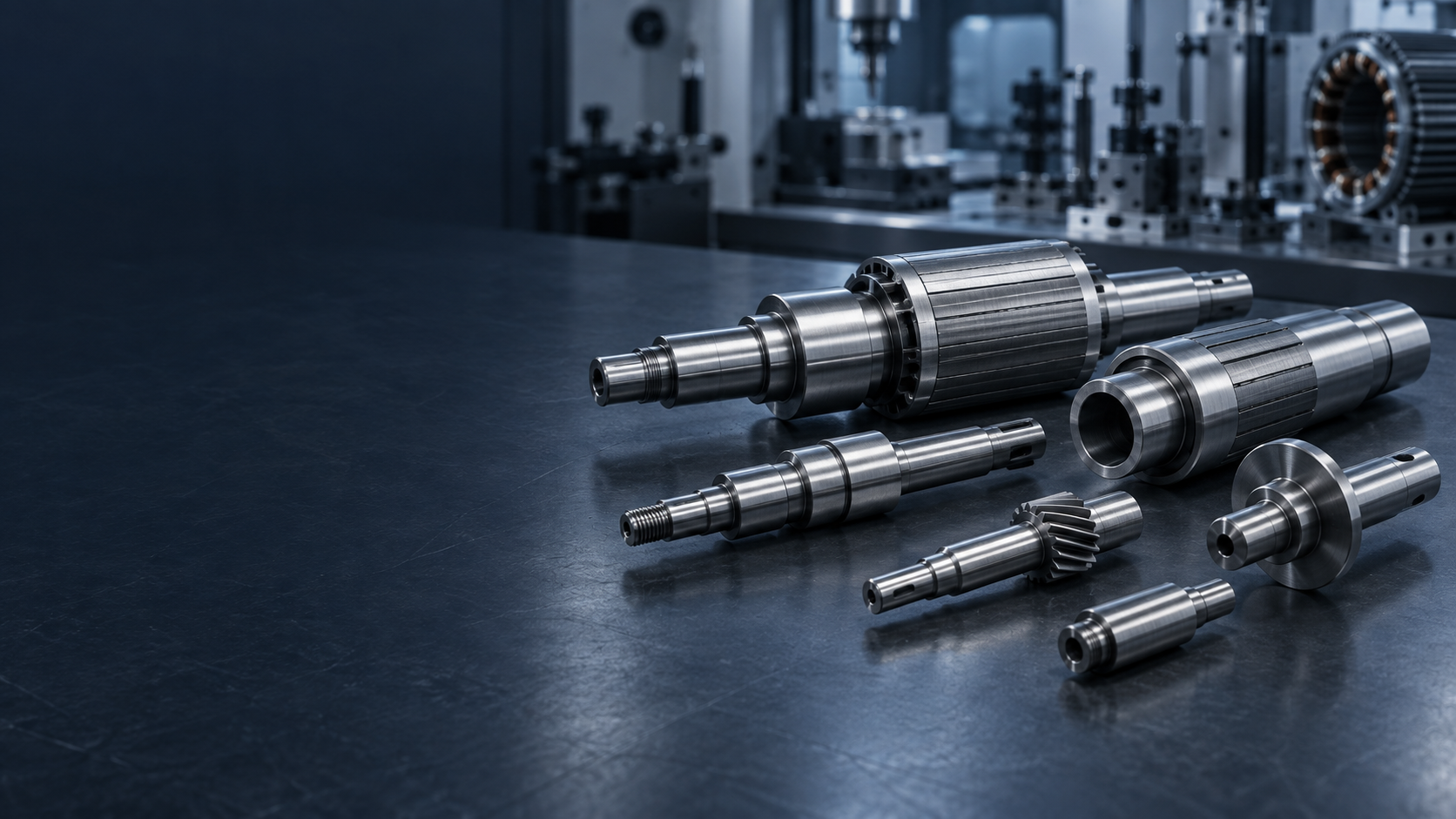
ELECTRIC MOTOR SHAFT MANUFACTURING
Motor Precision,
Built Around Motion.
Custom rotor, servo, BLDC, stepper and gearmotor shafts manufactured around bearing alignment, rotor fit, rotational accuracy and motor-specific operating requirements.ROTOR / BEARINGS / OUTPUT / RUNOUT / GRINDINGMOTOR SHAFT ENGINEERING SNAPSHOT
Precision Shafts For
Electric Motor Systems.
TOPSHAFT manufactures custom precision shaft components for electric motors, rotor assemblies, servo systems, BLDC motors, gearmotors and electromechanical drive systems. This industry page focuses on how a shaft functions across motor architectures, rather than duplicating the Motor Shaft product page.| Capability | TOPSHAFT support |
|---|---|
| Manufacturing focus | Custom precision shafts for electric motors, rotor assemblies, servo systems, gearmotors and electromechanical drive systems |
| Motor-system shaft roles | Rotor, output, encoder, pinion, spline, hollow, stepped and miniature shaft components |
| Processes | CNC and Swiss-type turning, milling, spline/gear features, heat treatment, grinding and inspection |
| Functional geometry | Bearing journals, rotor seats, shaft extensions, keyways, splines, threads, shoulders and feedback interfaces |
| Critical controls | Bearing fit, rotor fit, runout, concentricity, straightness, roundness, surface finish and alignment |
| Project support | Prototype, first article, pilot and repeat OEM production around approved drawing requirements |
PRECISION SHAFT SOLUTIONS FOR ELECTRIC MOTOR SYSTEMS
Designed Around
The Motor Architecture.
A motor shaft does more than transfer torque. It establishes the mechanical relationship between rotor, bearings, output connection and other functional components. The relevant drawing datums should follow that assembly role.ELECTRIC MOTOR SHAFT APPLICATIONS AT A GLANCE
Match The Shaft
To The Motor System.
Motor type, rotor architecture, bearing arrangement and driven load help define the shaft configuration and its functional inspection requirements.| Motor system | Typical shaft configuration | Key requirements |
|---|---|---|
| AC / induction motor | Rotor shaft with output extension | Bearing fit, straightness, rotor alignment |
| BLDC / PMSM | Precision motor / rotor shaft | Runout, concentricity, high-speed stability |
| Servo motor | Motor shaft with encoder/output interface | Low runout, bearing alignment, repeatability |
| Stepper motor | Small precision shaft | Diameter consistency, straightness, small features |
| Gearmotor | Motor pinion / gear shaft | Gear-to-bearing alignment, torque transmission |
| Pump motor | Coupling / output shaft | Bearing fit, alignment, corrosion requirements |
| Fan / blower motor | Rotor / output shaft | Rotational stability, runout |
| Electric actuator | Motor / spline / gear shaft | Compact geometry, fit, torque interface |
FUNCTIONAL ZONES OF AN ELECTRIC MOTOR SHAFT
One Shaft.
Several Functional Zones.
Each zone can have a different purpose and measurement requirement. The drawing should tie critical rotor and output features back to the functional bearing datums where appropriate.Output End → Keyway / Spline → Drive-End Bearing Journal → Rotor Mounting Section → Non-Drive-End Bearing Journal → Encoder / Auxiliary End
How the zones work together
- Bearing journals define the rotating support surfaces
- The rotor seat locates the rotor assembly around the shaft axis
- The output extension transfers torque to driven equipment
- Encoder interfaces can locate feedback components in servo systems
- Shoulders control axial location of bearings and rotor components
WHAT MAKES A PRECISION MOTOR SHAFT DIFFERENT?
The Shaft Defines
The Mechanical Axis.
The motor bearings support the shaft, and the rotor is located around that rotating system. Errors in functional geometry can contribute to vibration, bearing load, noise or rotor misalignment.Higher speed can increase sensitivity to
- Runout, straightness and concentricity
- Mass distribution and bearing-seat geometry
- Shaft stiffness, thermal effects, surface finish and assembly fit
ROTOR FIT & BEARING FIT
Functional, Not
Cosmetic Features.
The shaft should be manufactured to the customer's approved rotor and bearing datum requirements. A complete tolerance chain, not one dimension alone, defines the final rotor relationship to the stator.Rotor mounting can be specified as
- Press, bonded, keyed, splined or another engineered assembly method
- Rotor-seat relationship to bearing journals
- Output, coupling, pinion, pulley or fan interfaces
CRITICAL MOTOR SHAFT CHARACTERISTICS
Inspect The Features
That Affect Rotation.
Runout evaluates variation of a rotating surface relative to a defined datum axis. Concentricity or coaxial relationship describes the positional relationship between cylindrical axes. Use the drawing control that best reflects the actual motor assembly function.| CTQ | Why it matters |
|---|---|
| Drive-End Bearing Journal | Controls bearing fit |
| Non-Drive-End Journal | Establishes the second bearing support |
| Journal Roundness | Supports stable bearing contact |
| Cylindricity | Controls complete journal form |
| Journal-to-Journal Alignment | Helps define the rotor axis |
| Rotor Seat Diameter | Controls rotor fit |
| Rotor-to-Journal Runout | Influences rotor alignment |
| Shaft Straightness | Supports stable rotation |
| Output Shaft Runout | Influences connected equipment |
| Shoulder Position | Controls axial component location |
| Surface Roughness | Important for bearing and fitted surfaces |
| Keyway / Spline Geometry | Transfers torque |
| Hardness | Supports wear and fatigue requirements |
HIGH-SPEED MOTOR APPLICATIONS
Include RPM In
The Drawing Review.
As speed increases, bearing behavior, runout, shaft stiffness, thermal effects, rotor balance, lubrication and surface finish can become more significant. TOPSHAFT does not publish a universal maximum RPM because it depends on the complete rotor system.SHAFT ACCURACY VS. ROTOR BALANCE
Related, But
Not The Same.
A shaft can meet its component drawing requirements while the complete rotor assembly still requires dynamic balancing. The final rotating mass can include the shaft, laminations, magnets or cage, fan, encoder features and retaining components.Engineering distinction
- Component-level geometry supports assembly requirements
- Final rotor balance should be defined and validated at the complete assembly level
MATERIALS FOR ELECTRIC MOTOR SHAFTS
Chosen For The
Functional Load Case.
Material selection follows torque, fatigue, wear, corrosion, treatment and operating conditions. The final grade and condition should be stated on the drawing.Discuss Your Material Requirement →| Material | Typical direction | Engineering reason |
|---|---|---|
| 1045 / C45 | General industrial motor shafts | Strength and machinability |
| 4140 / 42CrMo | Higher-load motor shafts | Strength and toughness |
| 4340 | Demanding motor applications | Higher mechanical performance |
| 17-4PH stainless | Specialized precision shafts | Strength plus corrosion resistance |
| 304 / 316 stainless | Corrosive environments | Corrosion resistance |
| Hardenable stainless | Wear-critical specialized shafts | Hardness plus corrosion properties |
| Aluminum / specialty alloys | Lightweight application-specific designs | Reduced mass |
HEAT TREATMENT FOR MOTOR SHAFTS
Plan The Thermal Route
Around Functional Fits.
Critical bearing journals and rotor fits may be finish-machined or ground after thermal processing where required by the drawing.Potential routes
- Quenching and tempering for suitable alloy steels
- Induction hardening for selected journals, output interfaces or wear areas
- Nitriding for compatible steels where specified
- Age hardening for precipitation-hardening stainless steels
- Stress relieving where dimensional stability is important
WHY DOES MOTOR SHAFT STIFFNESS MATTER?
Loads Can Change
The Running Relationship.
Motor shafts can experience transmitted torque, rotor mass, coupling loads, belt/pulley loads or integral gear loads. Excessive deflection can alter the relationship among bearings, rotor and output interface.Useful application data
- Output connection: coupling, pulley, gear, pump or fan
- Radial, axial and torque loads where available
- Operating speed, duty cycle and motor architecture
ELECTRIC MOTOR SHAFT MANUFACTURING PROCESSES
Linked Processes
For Functional Geometry.
Turning, thermal processing and cylindrical grinding are not isolated processes. They can be planned as a chain to control bearing fits, rotor fits, runout and straightness around the drawing requirements.CNC Turning
Rotor seats, bearing journals, shoulders, shaft extensions, grooves and threads.
Swiss-Type Turning
Smaller motor shafts, slender geometry and high-repeatability small components.
CNC Milling
Keyways, D-flats, slots and cross holes.
Spline / Gear Machining
Geared motors, actuator motors and splined output interfaces.
Heat Treatment
Specified strength, toughness, hardness or stability requirements.
Precision Grinding
Selected bearing journals, rotor diameters, seal surfaces and precision fits.
FROM MOTOR DRAWING TO PRODUCTION SHAFT
Build The Route
Around The Datums.
Motor-system projects are reviewed around the customer's bearing, rotor, output, material, heat-treatment, operating-speed and inspection requirements. Final motor performance is verified by the customer in the complete assembly.- 01Motor Architecture & Drawing ReviewPlanned around the drawing and confirmed project requirements.
- 02Identify Bearing, Rotor & Output DatumsIdentify the functional relationship among bearing journals, rotor seat and output interfaces.
- 03Define CTQs & Manufacturing RoutePlanned around the drawing and confirmed project requirements.
- 04CNC Turning / Swiss MachiningPlanned around the drawing and confirmed project requirements.
- 05Keyway, Spline, Gear & Secondary FeaturesPlanned around the drawing and confirmed project requirements.
- 06Heat Treatment If RequiredPlanned around the drawing and confirmed project requirements.
- 07Precision GrindingPlanned around the drawing and confirmed project requirements.
- 08Runout, Geometry & Surface InspectionInspect runout, geometry, surface condition and drawing-specified features.
- 09Production & DocumentationPlanned around the drawing and confirmed project requirements.
Motor review → Bearing/rotor datums → Process plan → Machining → Treatment → Grinding → Inspection
FROM MOTOR DEVELOPMENT TO REPEAT PRODUCTION
Support The
Development Path.
Motor OEM projects can move from initial geometry review to a repeatable approved process while the customer validates the shaft in the complete rotor or motor assembly.Typical project stages
- Prototype: confirm basic shaft geometry and assembly
- First article: validate CTQs and inspection method
- Motor / rotor validation: customer verifies assembly performance
- Pilot batch: confirm process repeatability
- Production: maintain approved requirements across repeat orders
MOTOR SHAFT QUALITY CONTROL
Measure The
Functional Geometry.
Inspection methods are selected around the drawing and project requirements.Possible inspection controls
- Bearing and rotor-seat diameters, length and shoulder position
- Runout, roundness, cylindricity, straightness and journal relationship
- Keyway, spline, gear/pinion, thread and output interfaces
- Surface roughness, hardness and drawing-specific documents where agreed
DFM CONSIDERATIONS FOR ELECTRIC MOTOR SHAFTS
Define The Functional
Axis Early.
Good DFM input supports a more useful manufacturing review and helps target precision to functional surfaces.Useful engineering inputs
- Identify bearing seats and provide bearing information where helpful
- Define the rotor interface: fit, key, spline, adhesive or other method
- Control rotor/output runout relative to an appropriate bearing datum
- Provide operating RPM and output load details
- State material, treatment, hardness and ground surfaces
- Consider practical assembly sequence for rotor, bearings, spacers and retaining features
WHY TOPSHAFT FOR MOTOR-SYSTEM SHAFT MANUFACTURING
Motor-System Context,
Shaft-Focused Delivery.
Motor projects can bring rotor, bearing, output, gear, spline, treatment, grinding and inspection requirements into one drawing-led component route.Project approach
- Review the shaft within its motor architecture rather than as an isolated cylinder
- Support prototype, first article, pilot and repeat OEM production requirements
- Manufacture and inspect to the approved drawing and agreed quality requirements
- Keep the Motor Shaft product page focused on product-level features and this page on system context
WHAT INFORMATION IS NEEDED FOR A MOTOR SHAFT PROJECT?
Send The Data That
Defines The Motor System.
Complete motor, geometry, output, precision, material and commercial data enables a more useful engineering review.Upload Your Motor Shaft Drawing →| Information group | Include where available |
|---|---|
| Motor information | Motor type, AC/BLDC/PMSM/servo/stepper, operating and maximum RPM, application |
| Shaft geometry | Overall length, journals, rotor seat, shaft extension, shoulders, threads, grooves and hollow bore if applicable |
| Output interface | Keyway, spline, D-flat, gear/pinion, coupling seat or thread |
| Precision requirements | Bearing/rotor fit, runout, straightness, roundness, cylindricity, surface roughness and GD&T |
| Material & treatment | Material grade, heat treatment, hardness and surface treatment |
| Commercial requirements | Prototype and production quantity, annual demand, inspection documents and target delivery |
RELATED MOTOR SHAFT SOLUTIONS
Follow The Motor
Architecture.
01Motor ShaftCore motor and rotor components→02Hollow ShaftThrough-bore motor configurations→03Gear ShaftGearmotor pinion and gear features→04Helical Gear ShaftHelical reducer applications→05Spline ShaftSplined output interfaces→06Stepped ShaftMulti-diameter rotor shafts→07Threaded ShaftThreaded ends and retention→08Spindle ShaftMotorized spindle systems→09Gearbox IndustryGearmotor system requirements→10Automotive IndustryEV motor system applications→
View All Precision Shaft Products →MOTOR SHAFT FAQS
Answers For The
Motor Drawing Review.
Practical questions for electric motor OEM procurement, rotor engineers and motion-system teams.What shaft types are used in electric motors?+
Electric motor systems can use rotor shafts, output shafts, hollow shafts, geared or splined shafts, encoder shafts and custom stepped shafts depending on the motor architecture and driven load.
What is the difference between a motor shaft and a rotor shaft?+
A motor shaft may refer broadly to the shaft used in an electric motor. A rotor shaft emphasizes the functional section that locates and supports the rotor assembly. The exact terminology depends on the motor design.
What motor types can TOPSHAFT manufacture shafts for?+
Custom projects can be reviewed for AC, induction, BLDC, PMSM, servo, stepper, gearmotor, pump, fan, actuator and other motor-system shaft components.
Why is bearing-journal accuracy important on a motor shaft?+
The journals control the fit and rotating support relationship with the bearings. Their diameter, roundness, form, surface and alignment can affect assembly and operating performance.
Why does motor-shaft runout matter?+
Runout represents variation of a rotating surface relative to its reference axis. Excessive runout can contribute to rotor misalignment, vibration and poor alignment with connected equipment.
What materials are commonly used for electric motor shafts?+
Carbon steel, alloy steel and stainless steel are common choices, selected according to torque, fatigue, wear, corrosion, heat-treatment and operating requirements.
Can TOPSHAFT manufacture hollow motor shafts?+
Hollow motor shaft projects can be evaluated from bore geometry, wall thickness, rotor/bearing interfaces, material, critical features and drawing requirements.
Can motor shafts have gears, splines or keyways?+
Yes. Custom motor-system shaft projects can include drawing-specified keyways, splines, gear or pinion features and other output interfaces.
Can bearing journals be precision ground?+
Where specified, final grinding can control critical bearing, rotor, seal and other functional diameters after machining or thermal processing.
Can TOPSHAFT manufacture servo and BLDC motor shafts?+
Servo and BLDC shaft projects can be reviewed around rotor, bearing, encoder, output-interface, speed and critical geometry requirements.
Can you support miniature stepper motor shafts?+
Small shaft projects can be evaluated around diameter, slenderness, D-flat, keyway, thread, burr-control, surface and inspection requirements.
Can motor shafts be heat treated?+
Specified quench and temper, induction hardening, nitriding, age hardening or stress-relieving routes can be evaluated according to material and drawing requirements.
Can TOPSHAFT support prototype and repeat production?+
Projects can be reviewed from prototype and first article through pilot quantities and repeat OEM production based on the approved drawing and commercial requirements.
What information is required for a motor shaft quotation?+
Provide motor type, operating RPM, drawing/CAD, bearing and rotor interfaces, output features, precision requirements, material/treatment, quantity and documentation needs.
NEED A CUSTOM ELECTRIC MOTOR SHAFT?