
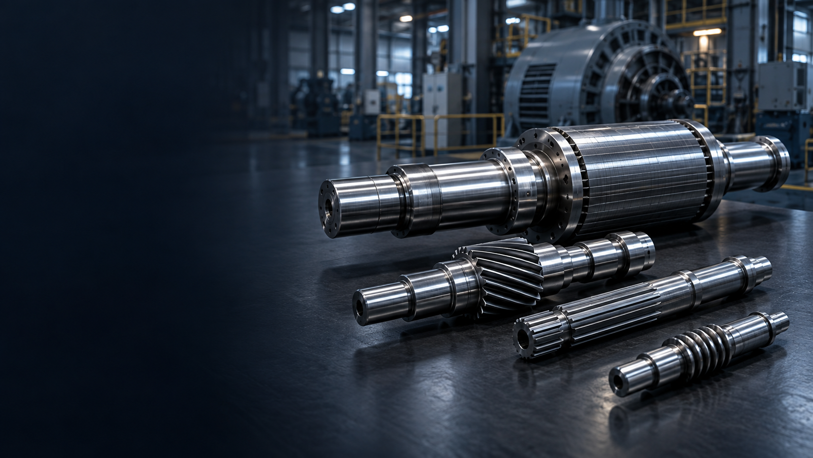
ENERGY EQUIPMENT SHAFT MANUFACTURING
Precision Shafts For
Energy & Power Generation.
Energy Precision, Engineered for Equipment. Custom generator, gearbox, drivetrain, worm, motor and turbine-related shaft components manufactured around bearing alignment, torque, fatigue, corrosion and energy-system operating requirements.GENERATORS / DRIVETRAINS / GEARS / WORMS / GRINDINGENERGY SHAFT CAPABILITY SNAPSHOT
Precision Components
For Mechanical Power.
TOPSHAFT manufactures custom precision shaft components for energy and power-generation equipment. The focus is the shaft's role in controlled mechanical power transfer—not unsupported claims around every large utility-scale turbine shaft.| Capability | TOPSHAFT support |
|---|---|
| Manufacturing focus | Custom precision shaft components for generators, renewable-energy drivetrains, hydro equipment, solar tracking and auxiliary systems |
| Shaft roles | Generator rotor, gear, spline, worm, motor, actuator, transmission and coupling shaft components |
| Functional geometry | Bearing journals, rotor and gear seats, splines, worms, keyways, shoulders, threads and bores |
| Critical controls | Runout, straightness, coaxiality, bearing fit, gear alignment, hardness, fatigue and corrosion requirements |
| Processes | CNC turning and milling, gear/spline/worm features, heat treatment, grinding, finishing and inspection |
| Project support | Prototype, engineering sample, legacy-component feasibility, first article and repeat OEM production |
PRECISION SHAFT SOLUTIONS FOR ENERGY EQUIPMENT
Built Around
The Energy System.
Energy equipment places shafts within generator, gearbox, hydro, solar-tracker and auxiliary-drive systems. The drawing needs to define the interfaces, loads and conditions that matter to that system.ENERGY EQUIPMENT SHAFT APPLICATIONS AT A GLANCE
Match The Shaft
To The Energy System.
A clear energy system → shaft component → engineering requirement relationship helps guide practical drawing review and RFQ information.| Energy system | Typical shaft components | Main engineering requirements |
|---|---|---|
| Generator | Rotor / generator shaft | Bearing fit, runout, straightness, rotor alignment |
| Wind drivetrain | Gearbox, transmission and gear shaft | Torque, fatigue, gear alignment, axial load |
| Wind generator | Generator shaft | Rotational accuracy, bearing alignment |
| Hydropower | Turbine/generator/coupling shaft | Shaft alignment, vibration, load support |
| Pumped storage | Motor-generator shaft | Bidirectional operation, bearings, alignment |
| Solar tracker | Worm, motor and drive shaft | Torque, corrosion, low-speed positioning |
| Energy gearbox | Input/intermediate/output shaft | Gear/spline fit, heat treatment |
| Plant auxiliary pump | Pump / motor shaft | Bearing fit, seal interface, corrosion |
| Actuator system | Motor / worm / spline shaft | Compact torque transmission and positioning |
HOW DO SHAFTS TRANSFER ENERGY?
Mechanical Rotation.
Controlled Interfaces.
Energy equipment turns mechanical rotation into useful electrical power or controlled motion. TOPSHAFT manufactures the drawing-defined shaft components that connect the relevant interfaces inside those systems.Wind Rotor → Main Shaft → Gearbox → High-Speed Shaft → Generator → Electric Power
Water Flow → Turbine → Turbine / Generator Shaft → Generator Rotor → Electric Power
Energy drivetrain context
- Generator shafts establish rotor and bearing relationships
- Gear, spline and helical shafts transfer torque through drivetrain stages
- Worm and actuator shafts support solar tracking motion
- Hydro and auxiliary systems can require long-life rotating interfaces
WHAT MAKES AN ENERGY EQUIPMENT SHAFT DIFFERENT?
Reliability Across
Long Service Duty.
Energy equipment can operate for long periods where downtime and access are costly. Material, fatigue, surface quality, bearing interfaces, heat treatment and inspection requirements should follow the actual load case.Energy-specific themes
- Long duty cycles and cyclic loading
- Rotational accuracy, fatigue and environmental exposure
- Remote, elevated, outdoor or water-adjacent service
COMBINED LOADS
Torque Is Only
One Part Of The Load.
Energy drivetrain shafts may experience torsion, bending, axial load and cyclic conditions. Wind and variable operating systems can create changing loads, while some pumped-storage configurations may involve reversing operation.Useful application inputs
- Continuous and peak torque
- Radial and axial loads where available
- Operating speed, duty cycle and environment
GENERATOR, GEARBOX & ROTATIONAL ACCURACY
Define The Support Axis.
Generator and high-speed gearbox components may require careful control of bearing journals, runout, straightness, mass distribution and gear-to-journal relationships. The drawing should tie controls to the functional bearing/support geometry.Typical critical interfaces
- Rotor seats and generator bearing journals
- Gear or spline interfaces and coupling ends
- Runout and coaxiality relative to specified datum axes
OUTDOOR & CORROSIVE ENVIRONMENTS
Specify The Exposure Condition.
Wind, hydro, outdoor solar trackers, cooling-water systems and coastal installations can introduce corrosion concerns. Material and surface protection should be selected around the operating environment and customer specification.Potential exposure data
- Outdoor, offshore, water, humidity and temperature context
- Surface-protection and coating requirement
- Material certificates where agreed
CRITICAL ENERGY SHAFT CHARACTERISTICS
Inspect The Features
That Transfer Power.
Final equipment performance is a system-level outcome. TOPSHAFT manufactures and inspects the shaft component against its approved drawing, relevant datums and agreed quality requirements.| CTQ | Why it matters |
|---|---|
| Bearing journal diameter | Controls bearing fit |
| Journal roundness | Supports stable rotation |
| Journal coaxiality | Defines the shaft line |
| Straightness | Important on long rotating shafts |
| Runout | Influences vibration and rotor alignment |
| Gear-to-journal alignment | Supports drivetrain gear mesh |
| Spline fit | Controls torque interface |
| Shaft shoulder position | Controls axial component location |
| Surface roughness | Important on bearings and seals |
| Hardness | Supports fatigue and wear requirements |
| Case depth | Important for hardened gear/spline features |
| Corrosion resistance | Relevant to outdoor and wet equipment |
MATERIALS FOR ENERGY EQUIPMENT SHAFTS
Selected For The Load And Environment.
Material selection follows transmitted load, fatigue, wear, treatment, corrosion exposure and the customer's specification. Specialty grades are reviewed only for compatible sourcing and machining requirements.Discuss Your Material Requirement →| Material direction | Typical use | Main consideration |
|---|---|---|
| 1045 / C45 | General drive components | Strength and machinability |
| 4140 / 42CrMo | Gearbox, generator and drive shafts | Strength and toughness |
| 4340 / high-strength alloy steel | Higher-load shaft components | Fatigue and strength |
| Carburizing alloy steel | Gear and spline shafts | Hard case plus tough core |
| 17-4PH stainless | High-strength corrosion-resistant applications | Strength plus corrosion resistance |
| 304 / 316 stainless | Wet or corrosive auxiliary systems | Corrosion resistance |
| Customer-specified alloys | Specialized energy systems | Load/environment-specific requirements |
HEAT TREATMENT FOR ENERGY SHAFTS
Plan The Thermal Route Around The Interfaces.
Critical bearing, gear and seal surfaces may receive finish machining or grinding after heat treatment when required by the drawing.Potential routes
- Quenching and tempering for high-load shaft components
- Carburizing for gear and spline shafts
- Induction hardening on localized journals or wear surfaces
- Nitriding for compatible material and wear requirements
- Stress relieving for long or complex machined components
CORROSION & SURFACE PROTECTION
Protect The Specified Service Surface.
Passivation, black oxide, zinc, nickel, electroless nickel and other coatings are project requirements, not automatic universal solutions.Review points
- Material and coating compatibility with the environment
- Effect of finish on critical fits and surfaces
- Customer-specified corrosion or salt-spray requirements
ENERGY EQUIPMENT SHAFT MANUFACTURING PROCESSES
Linked Processes For Power Transfer.
Turning, gear or worm features, treatment, grinding and inspection are planned as a connected route around the approved component drawing.CNC Turning
Bearing journals, stepped diameters, shaft extensions, shoulders and threads.
CNC Milling
Keyways, flats, bolt patterns and functional holes.
Gear & Spline Machining
Energy gearboxes, reducer shafts and torque-transfer interfaces.
Worm Machining
Solar tracker slew drives and actuator-system components.
Deep-Bore / Hollow Machining
Central passages and drawing-specified through-bore shafts.
Precision Grinding
Bearing journals, seal surfaces, heat-treated diameters and precision rotational features.
FROM ENERGY EQUIPMENT DRAWING TO PRODUCTION SHAFT
Build The Route Around The System.
Projects are reviewed around energy application, bearing and torque interfaces, material, treatment, critical geometry, environmental context and commercial requirements. The customer validates final system performance in the completed equipment.- 01Energy System & Drawing ReviewPlanned around the approved drawing and confirmed project requirements.
- 02Identify Bearings, Torque & Gear InterfacesIdentify functional bearing, torque, gear, spline, worm and coupling relationships.
- 03Define CTQs, Material & Heat TreatmentPlanned around the approved drawing and confirmed project requirements.
- 04CNC Shaft MachiningPlanned around the approved drawing and confirmed project requirements.
- 05Gear, Spline, Worm & Secondary FeaturesPlanned around the approved drawing and confirmed project requirements.
- 06Heat TreatmentPlanned around the approved drawing and confirmed project requirements.
- 07Precision Grinding & FinishingPlanned around the approved drawing and confirmed project requirements.
- 08Runout, Alignment & Surface InspectionInspect drawing-specified runout, alignment, surface and interface features.
- 09Prototype or Repeat ProductionPlanned around the approved drawing and confirmed project requirements.
System review → Datums & CTQs → Process plan → Machining → Treatment → Grinding → Inspection
PROTOTYPE, REPLACEMENT & OEM PRODUCTION
Support The Equipment Lifecycle.
Energy-equipment projects can move from prototype to controlled repeat supply, or begin with a suitable review of legacy documentation and existing samples.Typical project routes
- New equipment development: prototype, sample and validation batch
- Repeat OEM production: controlled revisions and recurring manufacturing
- Legacy components: drawing, documentation or sample feasibility review
- Final equipment validation remains with the customer
ENERGY SHAFT QUALITY CONTROL
Measure The Functional Features.
Inspection methods are selected around the drawing and agreed project requirements.Possible inspection controls
- Micrometers, CMM, dial indicators and optical measurement
- Bearing, rotor, gear, spline, worm and coupling interfaces
- Runout, straightness, coaxiality, roughness and hardness
- Material verification and agreed documentation
DFM FOR ENERGY EQUIPMENT SHAFTS
Define The Functional Requirements Early.
Good DFM information focuses precision, material and processing effort on features that affect the actual energy system.Helpful engineering inputs
- Energy system: wind, hydro, generator, solar or auxiliary equipment
- Operating and maximum RPM, continuous and peak torque
- Bearing locations, gear/spline/worm data and coupling interfaces
- Environmental exposure, material, treatment and case depth
- Functional datums for runout, coaxiality and straightness
WHY TOPSHAFT FOR ENERGY EQUIPMENT SHAFTS
Energy Context, Shaft-Focused Delivery.
TOPSHAFT combines drawing-led manufacturing with a practical view of the component's bearing, torque, drivetrain and environmental interfaces.Project approach
- Support generator, gearbox, hydro, solar-tracker and auxiliary-equipment shaft components
- Review verified-size capability instead of making unsupported large-turbine claims
- Manufacture and inspect to approved drawing requirements
- Support prototype, legacy feasibility, first article and repeat OEM production
WHAT INFORMATION IS NEEDED FOR AN ENERGY SHAFT QUOTE?
Send The Data That Defines The Equipment.
Complete system, operating, geometry, precision, material and commercial information enables a more useful engineering review.Upload Your Energy Shaft Drawing →| Information group | Include where available |
|---|---|
| Application | Wind, hydro, generator, solar, auxiliary equipment type and shaft function |
| Operating requirements | Operating/maximum RPM, continuous/peak torque, radial/axial load, duty cycle and environment |
| Shaft geometry | Overall length, bearing journals, rotor or gear seats, shoulders, threads, bores and coupling interfaces |
| Transmission features | Gear, spline, keyway, worm, coupling seat and flange details |
| Precision requirements | Runout, straightness, coaxiality, roundness, roughness, bearing fits and GD&T |
| Material / treatment | Material grade, treatment, hardness, case depth and surface protection |
| Commercial | Prototype/production quantity, annual demand, inspection documentation and target delivery |
RELATED ENERGY SHAFT SOLUTIONS
Follow The Energy Architecture.
01Motor ShaftGenerator and motor-rotor interfaces→02Gearbox IndustryEnergy drivetrain context→03Gear ShaftWind and energy gearbox features→04Helical Gear ShaftHelical transmission stages→05Spline ShaftTorque-transfer splines→06Transmission ShaftTransmission stages→07Worm ShaftSolar tracking drives→08Stepped ShaftGenerator and hydro shaft geometry→09Hollow ShaftThrough-bore designs→10Pump IndustryAuxiliary pumping systems→11Motor IndustryAuxiliary motor systems→
View All Precision Shaft Products →ENERGY EQUIPMENT SHAFT FAQS
Answers For The Energy Drawing Review.
Practical questions for renewable-energy OEMs, power-generation equipment teams and industrial buyers.What types of shafts are used in energy equipment?+
Energy equipment can use generator rotor, motor, gear, helical, spline, worm, transmission, actuator, coupling and custom shaft components. The correct component follows the equipment architecture and approved drawing.
What shafts are used in wind turbine drivetrains?+
A conventional geared wind drivetrain can include a low-speed main shaft, gearbox shafts, a high-speed shaft and a generator shaft. TOPSHAFT reviews verified-size custom shaft components rather than claiming every utility-scale main-shaft application.
Can TOPSHAFT manufacture wind gearbox shafts?+
Gearbox, gear, helical, spline, transmission and custom shaft projects can be reviewed around verified size capability, torque interfaces, material, treatment and drawing requirements.
What shaft components are used in generators?+
Generator systems can use rotor shafts, bearing journals, shaft extensions, coupling interfaces, exciter ends and other drawing-defined components.
Can TOPSHAFT manufacture hydropower shaft components?+
Custom hydro turbine-generator, coupling, motor-generator and auxiliary-drive shaft components can be reviewed around verified size capability and the customer's approved drawing.
What shafts are used in solar tracking systems?+
Solar tracking drives can use electric-motor shafts, worm shafts and other drive components inside mechanisms that rotate or tilt photovoltaic structures.
Can TOPSHAFT manufacture solar tracker worm shafts?+
Drawing-specified worm, motor, drive, stepped and gear shaft components can be reviewed for solar tracker and actuator drive applications.
What materials are used for energy equipment shafts?+
Material direction follows transmitted load, fatigue, wear, treatment, corrosion exposure and the customer's specification. Common options may include carbon/alloy steels and corrosion-resistant stainless or customer-specified grades.
Why is shaft runout important in generator systems?+
Runout represents variation of a rotating feature relative to a defined datum axis. It can affect the mechanical relationship among bearing journals, rotor and connected interfaces.
Why are energy gearbox shafts heat treated?+
Specified thermal routes can support required strength, toughness, surface hardness, fatigue resistance and wear performance at gears, splines, journals or other functional features.
Can bearing journals be precision ground?+
Where specified, final grinding can control selected bearing, seal, rotor and other functional diameters after machining or heat treatment.
Can TOPSHAFT support replacement energy-equipment shafts?+
Drawings, legacy documentation or existing samples can be reviewed for manufacturing feasibility. TOPSHAFT does not promise engineering recertification or safety-critical replication outside approved project scope.
What information is required for an energy shaft quotation?+
Provide the energy system, equipment type, shaft role, drawing/CAD, operating speed, torque/load data where available, interfaces, material, treatment, precision requirements, quantity and documentation needs.
NEED A CUSTOM ENERGY EQUIPMENT SHAFT?