
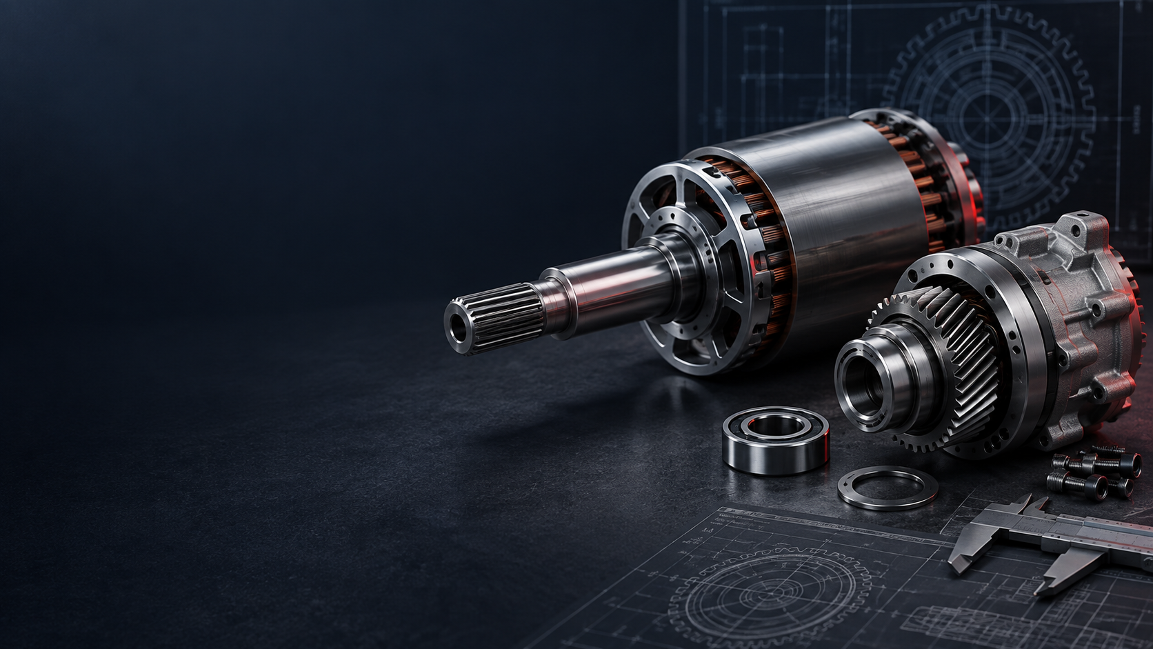
CUSTOM AUTOMOTIVE SHAFT MANUFACTURER
Automotive Precision,
Engineered To Move.
Custom precision shafts for automotive and electric-mobility systems—from EV motors and reduction gearboxes to transmissions, drivetrains, steering and internal-combustion powertrains.EV / HYBRID / ICE / OEM PROGRAMMESAUTOMOTIVE SHAFT MANUFACTURING CAPABILITIES
One Automotive Shaft
Never Fits Every System.
Automotive shafts operate where torque, rotational accuracy, fatigue, wear, vibration and assembly consistency matter. Each component is manufactured from the customer's drawing, 3D model and technical requirements using an appropriate combination of machining, treatment, finishing and inspection.| Capability | TOPSHAFT support |
|---|---|
| Manufacturing Type | Custom / OEM / Made to Drawing |
| Automotive Applications | EV motors, reducers, transmissions, drivetrains, steering, engines and auxiliary systems |
| Shaft Types | Motor, gear, spline, transmission, drive, stepped, hollow, camshaft, crankshaft and custom shafts |
| Machining | CNC turning, milling, Swiss-type machining, gear/spline machining and grinding |
| Materials | Carbon steel, alloy steel, stainless steel, carburizing steels and application-specific materials |
| Heat Treatment | Q&T, induction hardening, carburizing, nitriding and specified treatments |
| Critical Controls | Bearing fits, runout, coaxiality, straightness, gear/spline interfaces, hardness and surface finish |
| Production | Prototype through repeat OEM production |
| Inspection | Dimensional, geometric, surface and drawing-specific inspection |
| Documentation | Project-specific inspection and material documentation available according to agreed requirements |
PRECISION SHAFT SOLUTIONS FOR AUTOMOTIVE SYSTEMS
Built Around The
Rotating Assembly.
Functional load, rotational speed, bearing arrangement, torque path, material and tolerance requirements determine the shaft—not simply the outside profile.EV & HYBRID POWERTRAIN SHAFTS
From Rotor Datum
To Final Drive.
Electric powertrains combine motors, reduction gears, differentials and output stages within compact packages. Motor, hollow motor, gear, helical gear, spline, transmission and stepped shafts can all be evaluated around their functional interfaces.Battery ↓ Inverter ↓ Electric Motor ↓ Motor / Rotor Shaft ↓ Reduction Gearbox ↓ Gear / Spline / Transmission Shaft ↓ Final Drive
Critical EV relationships
High-accuracy bearing seats, rotor mounting surfaces, controlled concentricity, low runout, keyways, splines, threads and hollow sections are reviewed as a system.
Gear teeth ↔ bearing journals ↔ spline interface ↔ output datum
An EV shaft may meet nominal diameters and still create system problems if its functional features do not share the required rotational relationship.
TRANSMISSION & REDUCER SHAFTS
Follow The Complete
Torque Path.
Input, intermediate or countershafts, output shafts, integral gear shafts and spline connections can experience torsion, bending, cyclic fatigue, gear forces and bearing loads at the same time.- Bearing journal fits and gear-seat runout
- Spline geometry, shaft straightness and journal coaxiality
- Shoulder position, surface hardness and case depth
- Ground bearing surfaces and defined functional datums
AUTOMOTIVE SHAFT APPLICATIONS AT A GLANCE
Where Shaft Requirements
Change With The Vehicle.
| Automotive system | Typical shaft components | Common critical requirements |
|---|---|---|
| EV Traction Motor | Motor shaft, rotor shaft, hollow shaft | Runout, bearing fit, rotor alignment, high-speed stability |
| EV Reducer | Gear shaft, helical gear shaft, spline shaft | Gear accuracy, spline fit, journal alignment |
| Transmission | Input, intermediate, output shaft | Fatigue, bearing fits, gears, splines, coaxiality |
| Drivetrain | Drive shaft, spline shaft | Torque, straightness, connection geometry, rotational stability |
| Steering / EPS | Motor shaft, spline shaft, stepped shaft | Spline fit, alignment, runout |
| ICE Engine | Camshaft, crankshaft | Journal accuracy, hardness, wear, fatigue |
| Auxiliary Systems | Motor shaft, stepped shaft | Bearing fit, corrosion resistance, dimensional consistency |
WHAT MAKES AN AUTOMOTIVE SHAFT DIFFERENT?
More Than A
Turned Cylinder.
- 01Fatigue PerformanceRepeated bending, torsion and reversing loads make shoulders, fillets, spline roots, gear features, grooves and diameter transitions important.
- 02Rotational AccuracyRunout and feature alignment can influence vibration, noise, bearing life, gear contact, sealing and assembly.
- 03NVH PerformanceRunout, imbalance, shaft stiffness, bearing alignment, gear accuracy and rotational geometry all contribute to rotating-system behaviour.
- 04Weight & Rotational InertiaHollow designs or optimized geometries may reduce mass where structural and stiffness requirements permit.
- 05Wear ResistanceGear teeth, splines, bearing journals and seal surfaces may require hardened or precision-finished surfaces.
- 06Repeatable ProductionThe process is organised around the critical-to-quality features defined by the customer—not simply one conforming part.
CRITICAL AUTOMOTIVE SHAFT CHARACTERISTICS
Define The Features
That Affect Function.
The actual critical-to-quality features always follow the approved engineering drawing. These are common requirements for automotive shaft projects.Discuss Your Project →| Critical characteristic | Automotive function |
|---|---|
| Bearing Journal Diameter | Controls bearing fit |
| Runout | Supports stable rotation and reduced vibration |
| Coaxiality | Maintains alignment between functional diameters |
| Straightness | Important for rotating and assembled geometry |
| Roundness | Supports bearing and seal performance |
| Cylindricity | Controls complete journal form |
| Gear-to-Journal Alignment | Supports consistent gear mesh |
| Spline Fit | Controls torque transfer and assembly |
| Surface Roughness | Influences bearings, seals and wear surfaces |
| Hardness | Supports wear and fatigue requirements |
| Case Depth | Important on case-hardened functional surfaces |
| Shoulder Position | Controls axial component location |
| Thread Geometry | Controls retention and assembly interfaces |
MATERIALS & HEAT TREATMENT
Material, Surface And
Core Must Work Together.
Material selection should reflect load, fatigue, wear, heat treatment, corrosion and weight requirements—not simply the highest-strength alloy.| Material | Typical automotive shaft use | Main benefit |
|---|---|---|
| 1045 / C45 | General shafts and machinery components | Good strength and machinability |
| 4140 / 42CrMo | Transmission and drivetrain shafts | Strength, toughness and heat-treatment capability |
| 4340 | Higher-load components | High strength and fatigue resistance |
| Carburizing Alloy Steels | Gear and spline shafts | Hard wear-resistant surface with tougher core |
| 17-4PH Stainless Steel | Specialized precision components | Strength plus corrosion resistance |
| 304 / 316 Stainless Steel | Corrosion-sensitive components | Corrosion resistance |
| Aluminum Alloys | Lightweight specialized components | Reduced mass |
Quenching & Tempering
Increases overall strength and toughness for appropriate transmission and drivetrain requirements.
Carburizing
For suitable gear and spline steels requiring a hard surface with a tougher core.
Induction Hardening
Can selectively harden bearing journals, spline regions, shaft surfaces and localized wear areas.
Nitriding & Age Hardening
Specified treatments for suitable materials, including precipitation-hardening stainless steels.
Post-Treatment Finishing
Final turning or grinding allowance can be retained where treatment affects straightness, diameter, roundness or gear geometry.
AUTOMOTIVE SHAFT MANUFACTURING PROCESSES
Select The Route
For The Feature.
Different shaft types require different process combinations. The route is selected according to the functional requirements, geometry, material and inspection plan.CNC Turning
Bearing journals, stepped diameters, shoulders, grooves, threads and primary shaft geometry.
Swiss-Type Machining
Certain smaller or slender precision shaft components.
CNC Milling
Keyways, flats, holes, slots and special features.
Gear & Spline Machining
Gear shafts, helical gear shafts, spline shafts and transmission interfaces; route selected by geometry, material and accuracy.
Precision Grinding
Bearing journals, seal surfaces, hardened diameters and specified gear or spline features.
Secondary Processing
Heat treatment, plating, passivation, black oxide, polishing and protective coatings where specified.
FROM PROTOTYPE TO AUTOMOTIVE PRODUCTION
Review. Validate.
Repeat.
New projects generally progress through defined stages rather than moving directly into production volume.- 01Engineering ReviewConfirm manufacturability and critical requirements.
- 02PrototypeValidate geometry and function.
- 03First Article / SampleConfirm the manufacturing and inspection approach.
- 04Pilot / Validation BatchEvaluate repeatability and assembly.
- 05ProductionMaintain agreed specifications across repeated orders.
CNC turning → Milling / gear or spline machining → Heat treatment → Grinding → Surface finishing → Final inspection
AUTOMOTIVE QUALITY & PROCESS CONTROL
Quality Defined
By The Project.
Quality, inspection and documentation requirements are reviewed during quotation rather than assumed as one standard package.Possible controls
- Material certificates, grade information and traceability requirements
- In-process measurement of diameters, lengths, runout, gear/spline dimensions and journals
- Final inspection using appropriate micrometers, gauges, indicators, CMM, optical, roughness and hardness tools
- Agreed dimensional, first-article, material, treatment and surface-treatment records
AUTOMOTIVE SHAFT DFM CONSIDERATIONS
Make The Drawing
Work Harder.
A well-defined shaft drawing can improve manufacturability, cost and production stability.Useful DFM inputs
- Clearly identify bearing, gear, spline, seal and coupling fits
- Use functional datums that reflect rotation, assembly and load transfer
- Concentrate tight tolerances on features that affect function
- Specify material, treatment, hardness and case depth completely
- Identify post-treatment ground surfaces and relevant mating-component data
WHAT IS NEEDED FOR AN AUTOMOTIVE SHAFT QUOTE?
Send The Data That
Defines The Assembly.
For EV motor, gearbox and transmission projects, operating speed, torque and mating-component information are also useful where available.Upload Your Automotive Shaft Drawing →| Information | Examples |
|---|---|
| Drawing | 2D PDF / DWG / DXF |
| CAD | STEP / STP / IGES / X_T |
| Material | Grade and condition |
| Quantity | Prototype and production volume |
| Annual Demand | Estimated yearly requirement |
| Critical Fits | Bearings, gears, splines, seals |
| GD&T | Runout, straightness, coaxiality, etc. |
| Heat Treatment | Type, hardness, case depth |
| Surface Finish | Roughness / coating / plating |
| Documentation | FAI, certificates, inspection requirements |
| Application | EV motor, gearbox, drivetrain, steering, engine, etc. |
EXPLORE AUTOMOTIVE SHAFT SOLUTIONS
Product Families For
The Automotive System.
01Motor ShaftsEV traction motors, auxiliary motors and e-drive systems→02Gear ShaftsAutomotive transmissions and EV reducers→03Helical Gear ShaftsLow-noise reduction and transmission systems→04Spline ShaftsTorque-transfer and shaft-to-hub connections→05Transmission ShaftsGearbox input, intermediate and output stages→06Drive ShaftsDrivetrain torque-transfer components→07CamshaftsEngine valve-control systems→08CrankshaftsEngine and reciprocating power systems→
View All Precision Shaft Products →AUTOMOTIVE SHAFT FAQS
Questions Before
You Start.
Automotive applications require clear engineering inputs. These answers explain what to prepare before a drawing review.What automotive shafts can TOPSHAFT manufacture?+
Custom motor, rotor, gear, helical gear, spline, transmission, drive, stepped, hollow, camshaft, crankshaft and other made-to-drawing automotive shaft components can be evaluated.
What shafts are used in electric vehicles?+
Depending on the e-drive architecture, EVs can use motor and rotor shafts, reducer input and output shafts, gear shafts, helical gear shafts, spline shafts, transmission shafts and other rotating components.
What tolerances are important for automotive shafts?+
Critical requirements depend on function. Common examples include bearing-journal diameter, runout, coaxiality, straightness, roundness, cylindricity, roughness, gear or spline geometry and shoulder position.
What materials are commonly used?+
Carbon steel, alloy steel, carburizing steel and stainless steel are common. Lightweight materials can also be considered for specialized applications when the design permits.
Can automotive shafts be heat treated?+
Depending on material and application, specified treatments may include quenching and tempering, induction hardening, carburizing, nitriding or other treatments.
Can TOPSHAFT manufacture EV motor and rotor shafts?+
Custom projects can be reviewed from customer drawings, bearing interfaces, rotor mounting requirements, material, runout, surface finish and production quantity.
Can TOPSHAFT manufacture automotive gear and spline shafts?+
Gear, helical gear and spline shaft projects can be evaluated from supplied tooth geometry, shaft interfaces, material, heat treatment and inspection requirements.
Can TOPSHAFT support automotive prototypes?+
Projects can begin with prototypes, engineering samples or validation quantities before progressing to repeat manufacturing.
What automotive quality documents can be provided?+
Available documentation depends on the confirmed project scope and may include dimensional reports, material certificates, heat-treatment certificates, first-article documentation and customer-defined quality records.
Does TOPSHAFT support PPAP?+
PPAP and other automotive-specific quality documentation must be reviewed and confirmed project by project before order acceptance.
What information should I provide for quotation?+
Send the 2D drawing or 3D model, material, quantity, annual volume, critical fits and GD&T, heat treatment, surface finish and documentation requirements. Operating speed and torque data are also useful for drivetrain or EV projects.
NEED A CUSTOM AUTOMOTIVE SHAFT?